Engineering
Engineering beyond the equipment.
LINKWAVE engages before procurement. The work starts from a thermal load and a set of constraints, and ends with a commissioned system.
- 01Define
- 02Model
- 03Engineer
- 04Build
- 05Test
- 06Deploy
- 07Support
01 Define
Requirements definition
A cooling architecture is only as good as its inputs. These are the figures we ask for first.
- IT load
- Rack density
- Fluid conditions
- Facility water temperatures
- Pressure requirements
- Redundancy
- Environment
- Interfaces
02 Model
Thermal and hydraulic engineering
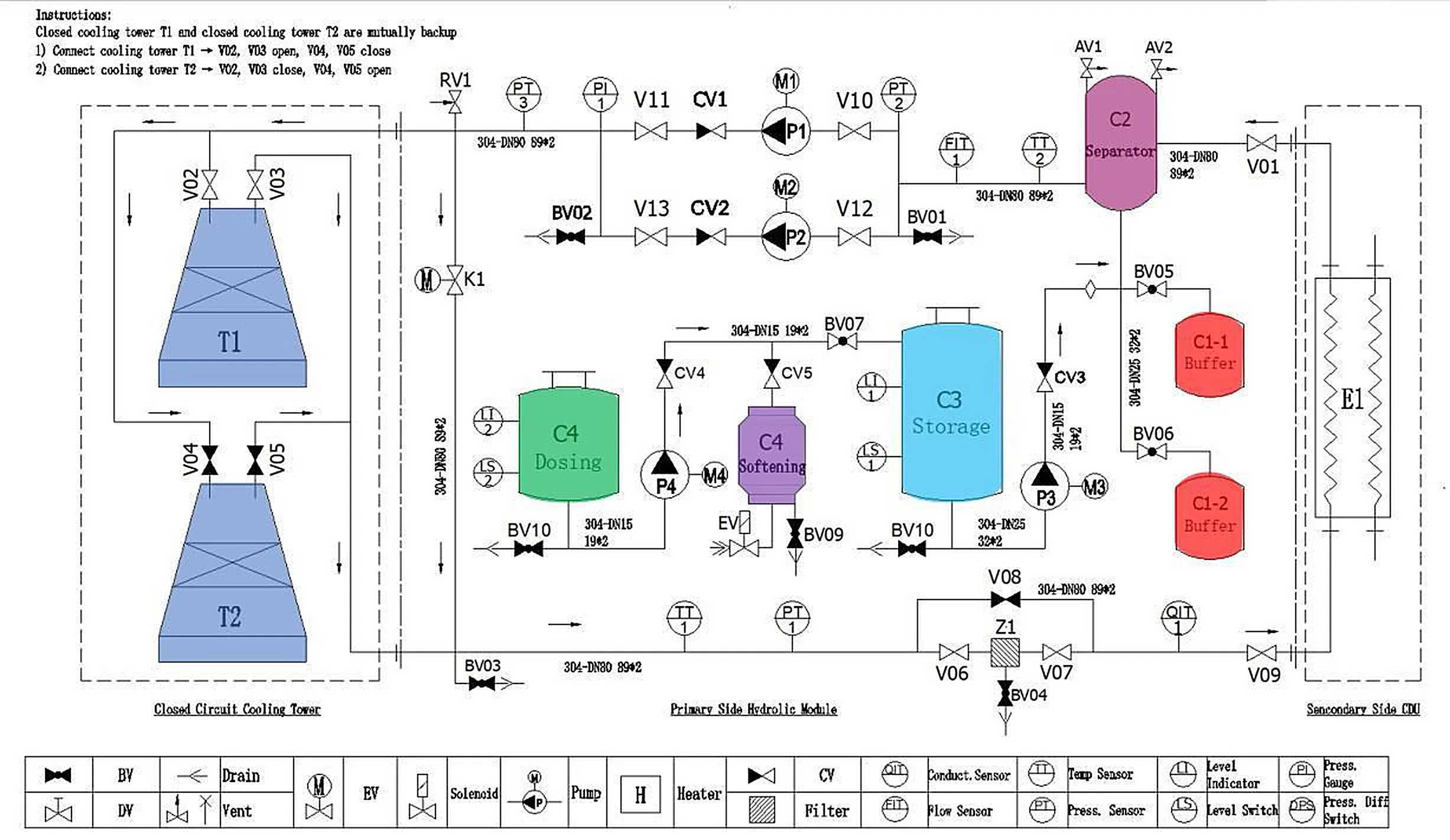
Each proposal is backed by a design calculation document, a layout plan and a process flow diagram. Where the budget is fixed, the configuration is optimized within it.
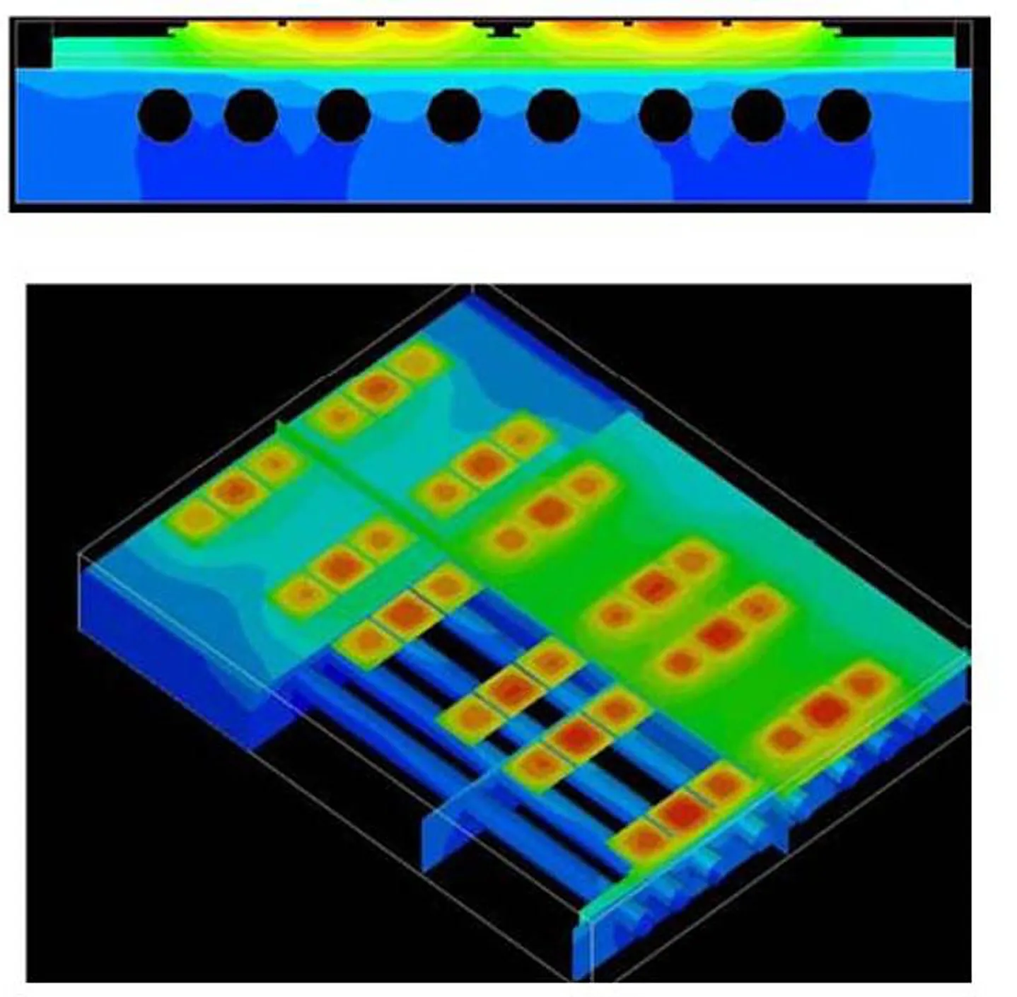
Simulation
CFD and simulation
Cold-plate and flow-path designs are developed in CAD and verified by CFD before hardware is built. The team has applied this workflow to liquid cold plates since its power-electronics work.
03 Engineer
System architecture
Primary loop, secondary loop and IT loop are designed together, so the conditions at each boundary are set once and agreed.
IT loop
01 / 09 · Heat source
GPU / CPU
By others
Processor heat flux sets every downstream requirement: coolant supply temperature, flow per server and allowable pressure drop.
02 / 09 · Chip-to-liquid heat transfer
Cold plate
Interface
Coolant passes through a plate mounted on the processor. Its flow and pressure-drop figures are the design inputs for the manifold and CDU.
03 / 09 · In-rack distribution
Rack manifold
LINKWAVE scope
A stainless manifold in each rack divides supply flow between servers and collects the return through 12 mm EPDM hoses.
View productSecondary loop
04 / 09 · Local coolant distribution
Rack / in-row CDU
LINKWAVE scope
Where load is distributed or facility water is unavailable, a CDU at the rack or row conditions and circulates coolant close to the IT equipment.
05 / 09 · Technology cooling system
Secondary cooling loop
LINKWAVE scope
Sanitary-grade stainless aisle piping carries treated water between the racks and the CDU. Typical supply and return: 40 / 55 °C.
View product06 / 09 · Loop isolation and control
Centralized CDU
LINKWAVE scope
A plate heat exchanger separates the IT loop from facility water. Dual variable-speed pumps hold flow and pressure. Reference units: 500 kW and 2.5 MW.
View productPrimary loop
07 / 09 · Facility water system
Primary cooling loop
LINKWAVE scope
Facility water carries heat from the CDUs to the heat-rejection plant. Water quality is managed by make-up, dosing and filtration on this side.
08 / 09 · Primary circulation
Primary-side pump station
LINKWAVE scope
Skid-built pumps with variable-frequency drives, storage, make-up and dosing. 125 kW to 2.5 MW, 10–250 m³/h.
View product09 / 09 · Heat rejection
Dry cooler / cooling tower / chilled water
Interface
Three reference arrangements: isolated CDU with chilled water; isolated CDU with cooling tower and pump station; direct-connected CDU with dry cooler and online purification.
Heat travels from chip to heat rejection. Select a stage for detail.
Controls
Controls
Control cabinets and the operator interface are designed and built in-house, together with the electrical schematics for each system.
- Operator interface
- HMI designed per project, with process mimic, set-points, events and alarms.
- Variable-frequency control
- Pump speed follows load. Heat-rejection fan speed follows load and ambient temperature.
- Monitoring and alarms
- Flow, pressure, temperature and water-quality instrumentation, with alarms on abnormal conditions such as leakage or a blocked filter.
- Communication
- Ethernet / Modbus communication is available as an option for integration with site monitoring.
Reliability
Reliability
Reliability is addressed in the hydraulic design and in how the equipment is built.
- Pump redundancy
- Redundant pumps that can be replaced while the unit is online.
- Bypass
- Filter bypass, so filtration is serviced without interrupting flow.
- Serviceability
- Valve positions chosen for access, and an open-type control cabinet.
- Component selection
- Redundant design for core components, with parts from established suppliers.
- Clean assembly
- Sanitary-grade stainless piping, electropolished, with no thread tape or sealant.
- Water quality
- Online water-quality monitoring, make-up, dosing and purification where the design calls for them.
04–05 Build and test
Build and factory acceptance
Delivery runs through seven controlled stages. Each closes before the next begins.
- T0
Order confirmation
- Requirement decomposition
- Bill of materials
- Delivery plan
- T1
Detailed design
- Structural design
- Electrical design
- Delivery documentation
- T2
Procurement
- Designed parts
- Catalogue parts
- Schedule control
- T3
In-house fabrication
- Sheet metal
- Piping
- Control box
- T4
Assembly and wiring
- Component assembly
- Final assembly
- Wiring
- T5
Testing and acceptance
- Performance testing
- Functional testing
- Factory acceptance test
- T6
Packaging and shipping
- Packaging design
- Logistics selection
06–07 Deploy and support
Commissioning and support
Support is described here as scope, not geography. Local service arrangements are agreed per project.
- Commissioning and training
- Commissioning and operator training at first operation of the unit.
- Remote diagnosis
- Remote fault diagnosis and maintenance guidance from the engineering team.
- Spare parts
- Parts are common across the series and kept in stock for long-term supply.
Have a load and a set of constraints?
That is enough to start. Send what you have, and an engineer will come back with an architecture and the questions that need answering.