Primary-side pump stations
Skid-built pump stations that circulate facility water between the CDUs and the heat-rejection plant, with make-up, storage and water treatment integrated.
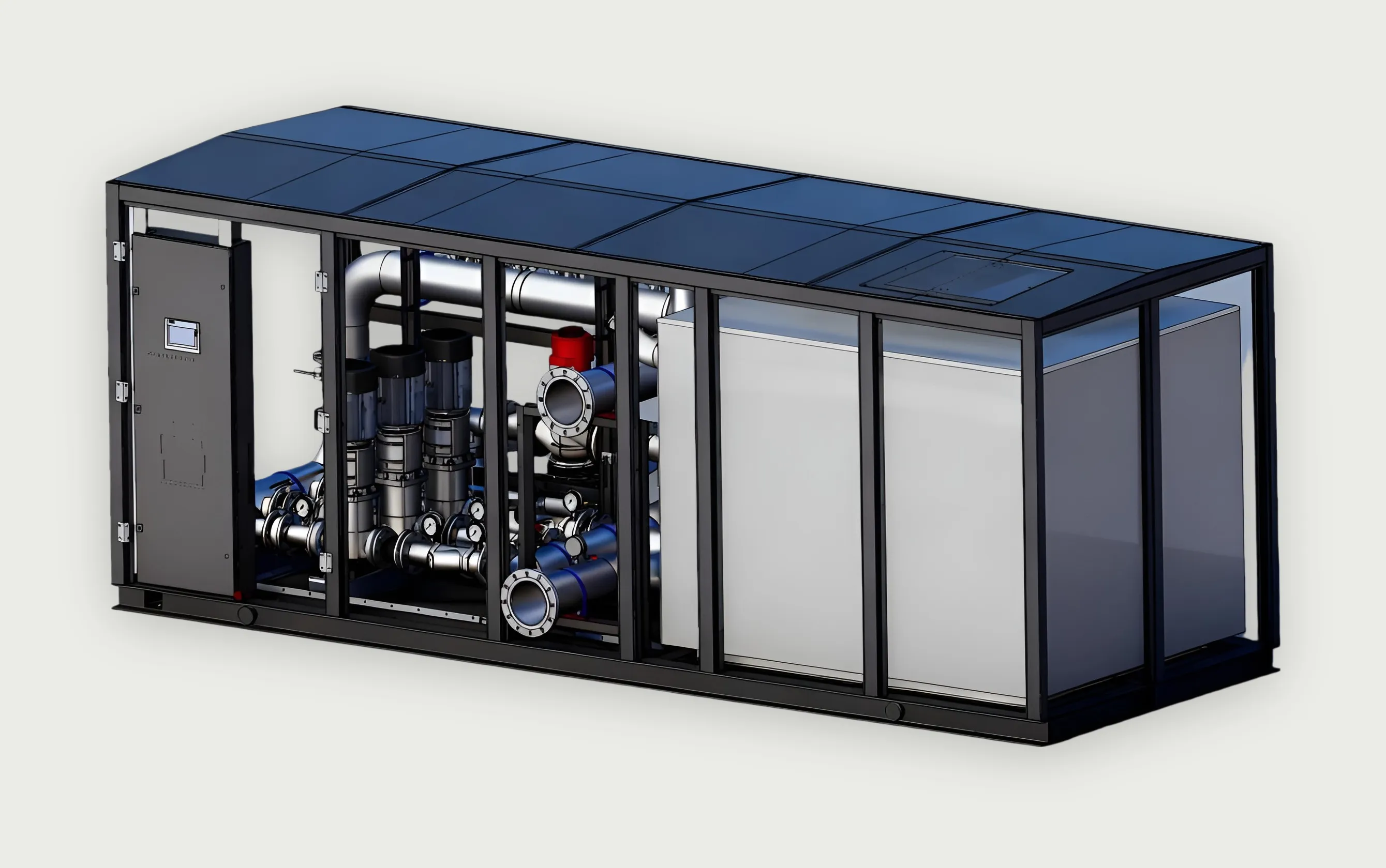
- Heat dissipation range
- 125–2,500kW
- Flow range
- 10–250m³/h
- Pressure range
- 1–5bar
- Operating temperature
- 30–55°C
System role
Where it sits in the system.
Moves heat from the centralized CDUs to dry coolers, cooling towers or a chilled-water plant, and holds primary-loop temperature under changing load.
IT loop
01 / 09 · Heat source
GPU / CPU
By others
Processor heat flux sets every downstream requirement: coolant supply temperature, flow per server and allowable pressure drop.
02 / 09 · Chip-to-liquid heat transfer
Cold plate
Interface
Coolant passes through a plate mounted on the processor. Its flow and pressure-drop figures are the design inputs for the manifold and CDU.
03 / 09 · In-rack distribution
Rack manifold
LINKWAVE scope
A stainless manifold in each rack divides supply flow between servers and collects the return through 12 mm EPDM hoses.
View productSecondary loop
04 / 09 · Local coolant distribution
Rack / in-row CDU
LINKWAVE scope
Where load is distributed or facility water is unavailable, a CDU at the rack or row conditions and circulates coolant close to the IT equipment.
05 / 09 · Technology cooling system
Secondary cooling loop
LINKWAVE scope
Sanitary-grade stainless aisle piping carries treated water between the racks and the CDU. Typical supply and return: 40 / 55 °C.
View product06 / 09 · Loop isolation and control
Centralized CDU
LINKWAVE scope
A plate heat exchanger separates the IT loop from facility water. Dual variable-speed pumps hold flow and pressure. Reference units: 500 kW and 2.5 MW.
View productPrimary loop
07 / 09 · Facility water system
Primary cooling loop
LINKWAVE scope
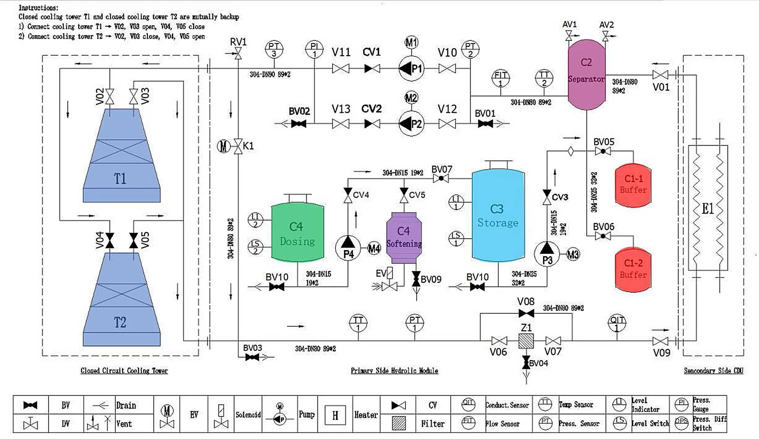
Facility water carries heat from the CDUs to the heat-rejection plant. Water quality is managed by make-up, dosing and filtration on this side.
08 / 09 · Primary circulation
Primary-side pump station
LINKWAVE scope
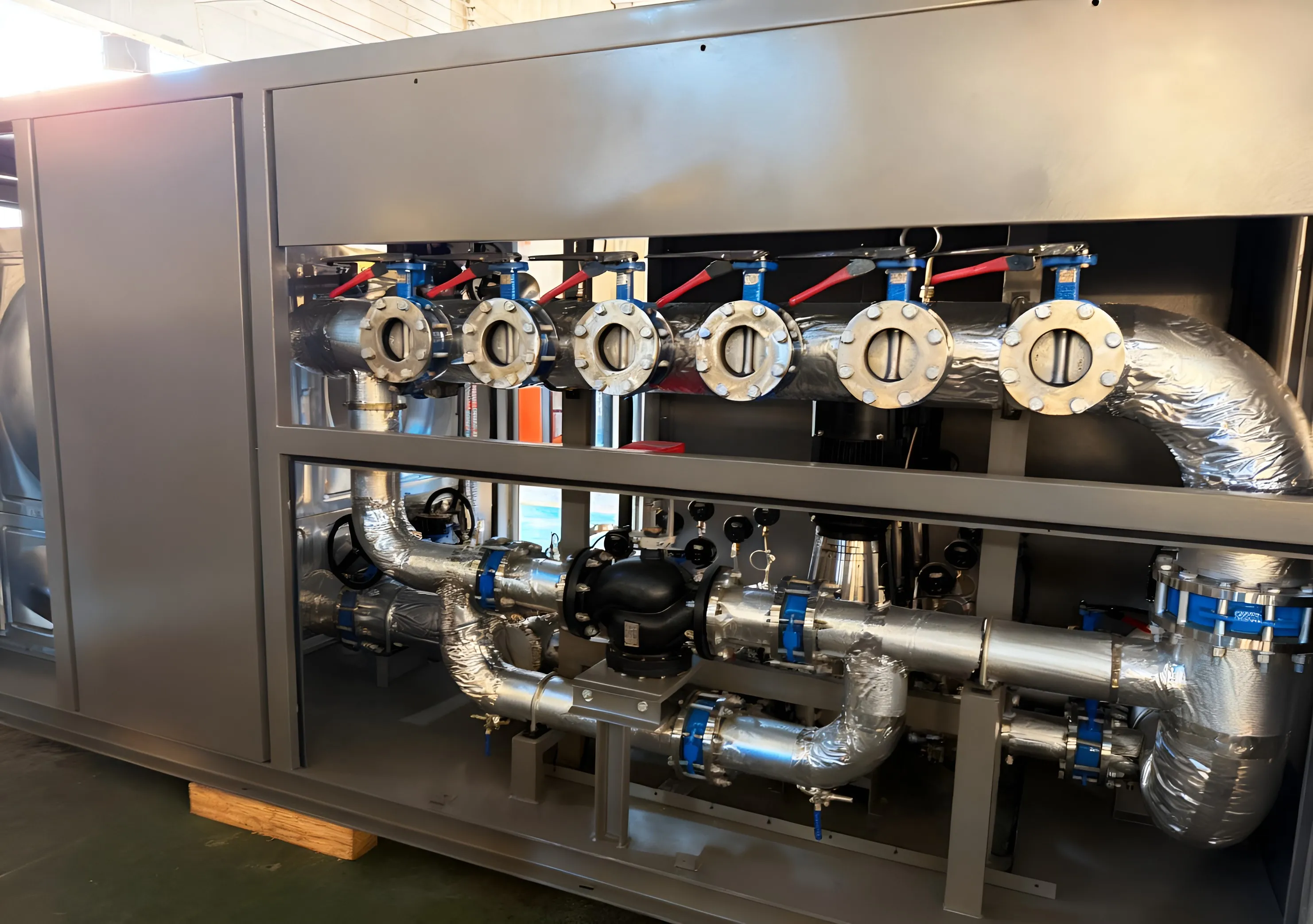
Skid-built pumps with variable-frequency drives, storage, make-up and dosing. 125 kW to 2.5 MW, 10–250 m³/h.
View product09 / 09 · Heat rejection
Dry cooler / cooling tower / chilled water
Interface
Three reference arrangements: isolated CDU with chilled water; isolated CDU with cooling tower and pump station; direct-connected CDU with dry cooler and online purification.
Heat travels from chip to heat rejection. Select a stage for detail.
Engineering highlights
Variable-frequency pumping with closed-loop load feedback.
- Variable-frequency pumping
- Pump speed and heat-rejection fan speed follow the real-time load and ambient temperature.
- Pump redundancy
- Parallel or 1+1 circulation pumps, configured to the project’s redundancy requirement.
- Integrated water management
- Storage tank, automatic make-up and dosing can be built into the skid.
- Closed-loop control
- Load feedback and pressure balancing hold supply conditions steady across multiple circuits.
Technical specifications
Specifications
SI units, with US customary equivalents where useful. Values are for the reference configurations shown; project units are sized to the load.
Thermal
| Maximum heat dissipation | 125 kW – 2,500 kW |
|---|---|
| Operating temperature | 30–55 °C86–131 °F |
Hydraulic
| Flow rate | 10–250 m³/h44–1,100 US gpm |
|---|---|
| Pressure | 1–5 bar14.5–72.5 psi |
| Medium | Deionized water ¹ |
Mechanical
| Dimensions | Sized to capacity |
|---|---|
| Weight | 200–1,500 kg441–3,307 lb |
Electrical
| Supply | 3-phase, 380–480 V, 50/60 Hz |
|---|
Controls
| Control mode | Variable frequency |
|---|---|
| Communication | Ethernet / Modbus (optional) |
Environmental
| Ambient temperature | −25 to 40 °C−13 to 104 °F |
|---|---|
| Relative humidity | 5–95 % |
| Altitude | ≤ 3,000 m≤ 9,840 ft |
¹ Where freeze protection is required, an ethylene-glycol or propylene-glycol solution is used, selected for the site’s ambient temperature.
Sizing this system for your load?
Send the heat load, flow and temperature requirements. An engineer will respond with a configuration and the open questions.