Centralized CDU
Liquid-to-liquid coolant distribution units that isolate the technology cooling loop from facility water and serve a row, a room or a full compute block from one unit.
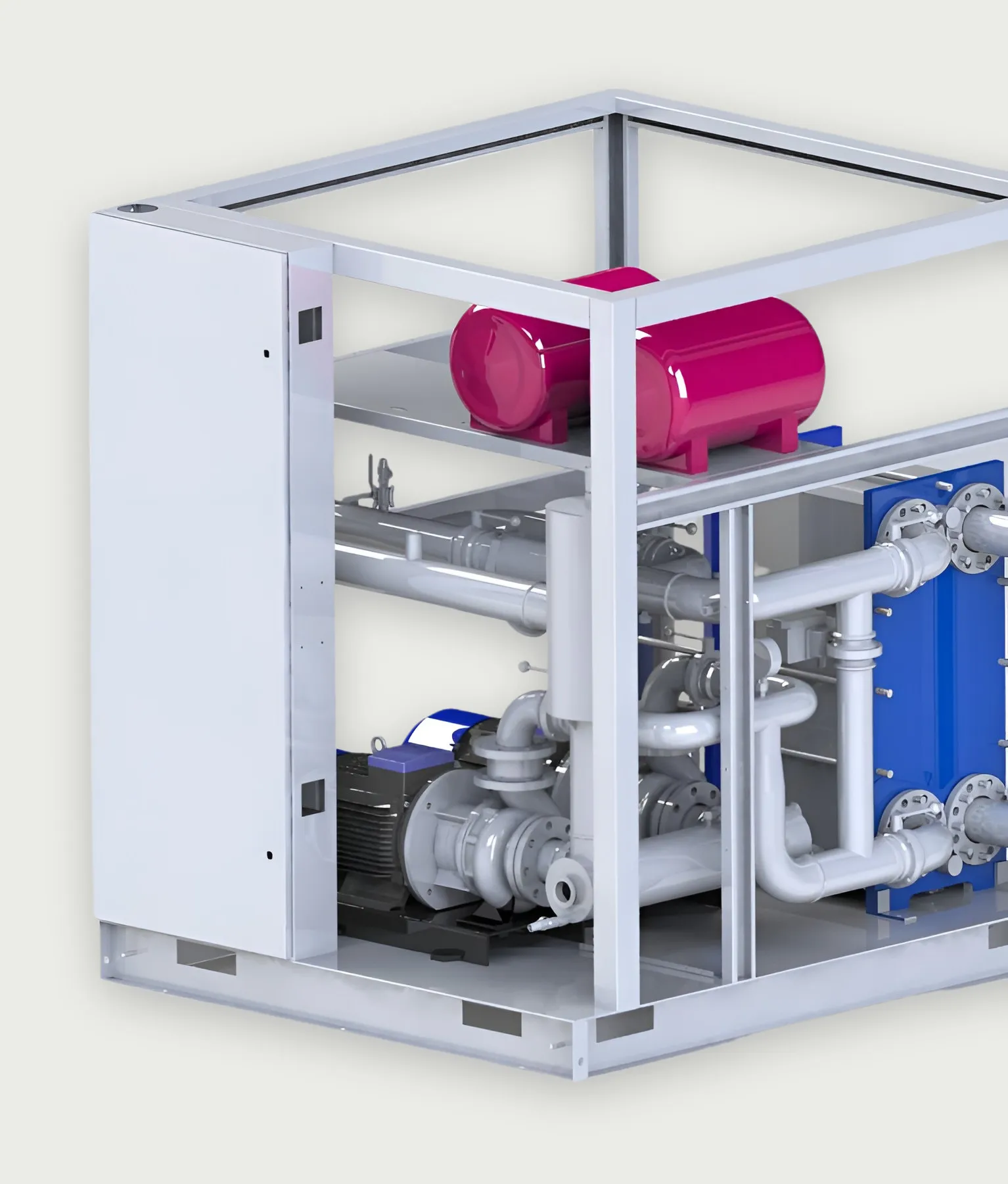
- Maximum heat dissipation
- 2.5MW
- Flow range, 2.5 MW unit
- 50–250m³/h
- Pressure
- 3bar
- Typical inlet / outlet
- 40 / 55°C
System role
Where it sits in the system.
Separates the secondary (IT) loop from the primary (facility) loop through a plate heat exchanger, and controls secondary flow, pressure and supply temperature.
IT loop
01 / 09 · Heat source
GPU / CPU
By others
Processor heat flux sets every downstream requirement: coolant supply temperature, flow per server and allowable pressure drop.
02 / 09 · Chip-to-liquid heat transfer
Cold plate
Interface
Coolant passes through a plate mounted on the processor. Its flow and pressure-drop figures are the design inputs for the manifold and CDU.
03 / 09 · In-rack distribution
Rack manifold
LINKWAVE scope
A stainless manifold in each rack divides supply flow between servers and collects the return through 12 mm EPDM hoses.
View productSecondary loop
04 / 09 · Local coolant distribution
Rack / in-row CDU
LINKWAVE scope
Where load is distributed or facility water is unavailable, a CDU at the rack or row conditions and circulates coolant close to the IT equipment.
05 / 09 · Technology cooling system
Secondary cooling loop
LINKWAVE scope
Sanitary-grade stainless aisle piping carries treated water between the racks and the CDU. Typical supply and return: 40 / 55 °C.
View product06 / 09 · Loop isolation and control
Centralized CDU
LINKWAVE scope
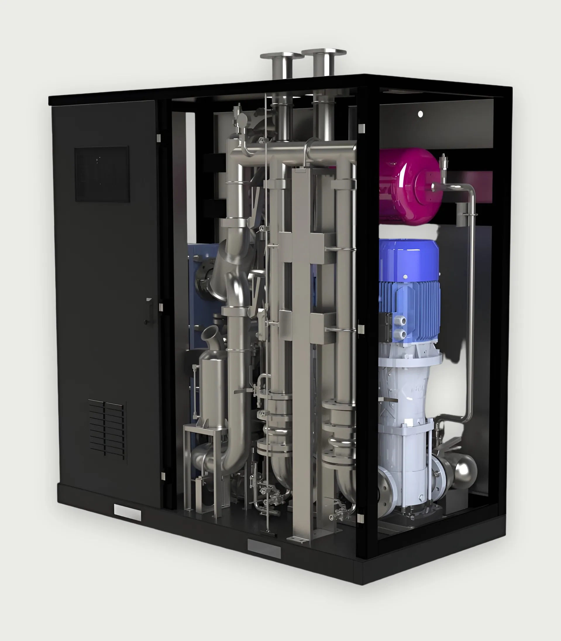
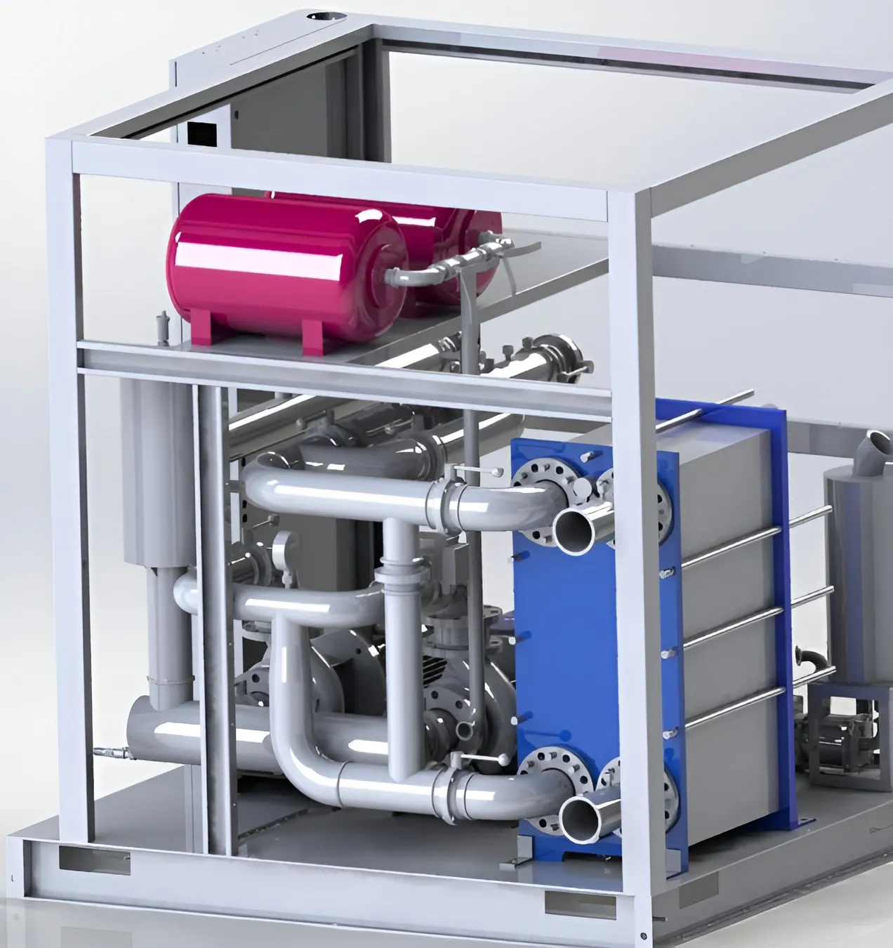
A plate heat exchanger separates the IT loop from facility water. Dual variable-speed pumps hold flow and pressure. Reference units: 500 kW and 2.5 MW.
View productPrimary loop
07 / 09 · Facility water system
Primary cooling loop
LINKWAVE scope
Facility water carries heat from the CDUs to the heat-rejection plant. Water quality is managed by make-up, dosing and filtration on this side.
08 / 09 · Primary circulation
Primary-side pump station
LINKWAVE scope
Skid-built pumps with variable-frequency drives, storage, make-up and dosing. 125 kW to 2.5 MW, 10–250 m³/h.
View product09 / 09 · Heat rejection
Dry cooler / cooling tower / chilled water
Interface
Three reference arrangements: isolated CDU with chilled water; isolated CDU with cooling tower and pump station; direct-connected CDU with dry cooler and online purification.
Heat travels from chip to heat rejection. Select a stage for detail.
Engineering highlights
Dual-pump, isolated design in cabinet and frame-mounted formats.
- Isolated loops
- A plate heat exchanger separates facility water from the technology cooling loop, so secondary water quality is controlled independently of the primary side.
- Dual pumps
- Two circulation pumps per unit. The redundant pump arrangement allows a pump to be replaced while the unit stays online.
- Variable-frequency control
- Pump speed follows the real-time load rather than running at fixed duty.
- Filter bypass
- The filter can be serviced through a bypass without interrupting coolant flow.
- Sanitary-grade piping
- Stainless-steel process piping, electropolished, assembled without thread tape or sealant.
Technical specifications
Specifications
SI units, with US customary equivalents where useful. Values are for the reference configurations shown; project units are sized to the load.
Thermal
| Parameter | 500 kW · cabinet | 2.5 MW · frame-mounted |
|---|---|---|
| Maximum heat dissipation | 500 kW | 2.5 MW |
| Inlet / outlet water temperatureTypical value | 40 / 55 °C104 / 131 °F | 40 / 55 °C104 / 131 °F |
Hydraulic
| Parameter | 500 kW · cabinet | 2.5 MW · frame-mounted |
|---|---|---|
| Flow rate | 5–90 m³/h22–396 US gpm | 50–250 m³/h220–1,100 US gpm |
| Pressure | 3 bar43.5 psi | 3 bar43.5 psi |
| Medium | Pure / deionized water ¹ | Pure / deionized water ¹ |
| Pump configuration | Dual pump | Dual pump |
Mechanical
| Parameter | 500 kW · cabinet | 2.5 MW · frame-mounted |
|---|---|---|
| Format | Enclosed cabinet | Open frame |
| Dimensions (W × D × H) | 2,000 × 1,000 × 2,000 mm78.7 × 39.4 × 78.7 in | 1,600 × 1,800 × 1,860 mm63.0 × 70.9 × 73.2 in |
| Weight | 350 kg772 lb | 850 kg1,874 lb |
Electrical
| Parameter | 500 kW · cabinet | 2.5 MW · frame-mounted |
|---|---|---|
| Supply | 3-phase, 380–480 V, 50/60 Hz | 3-phase, 380–480 V, 50/60 Hz |
Controls
| Parameter | 500 kW · cabinet | 2.5 MW · frame-mounted |
|---|---|---|
| Communication | Ethernet / Modbus (optional) | Ethernet / Modbus (optional) |
Environmental
| Parameter | 500 kW · cabinet | 2.5 MW · frame-mounted |
|---|---|---|
| Ambient temperature | −25 to 40 °C−13 to 104 °F | −25 to 40 °C−13 to 104 °F |
| Relative humidity | 5–95 % | 5–95 % |
| Altitude | ≤ 3,000 m≤ 9,840 ft | ≤ 3,000 m≤ 9,840 ft |
¹ Where freeze protection is required, an ethylene-glycol or propylene-glycol solution is used, selected for the site’s ambient temperature.
Sizing this system for your load?
Send the heat load, flow and temperature requirements. An engineer will respond with a configuration and the open questions.