Modular AI Infrastructure
Cooling plant that arrives integrated and tested.
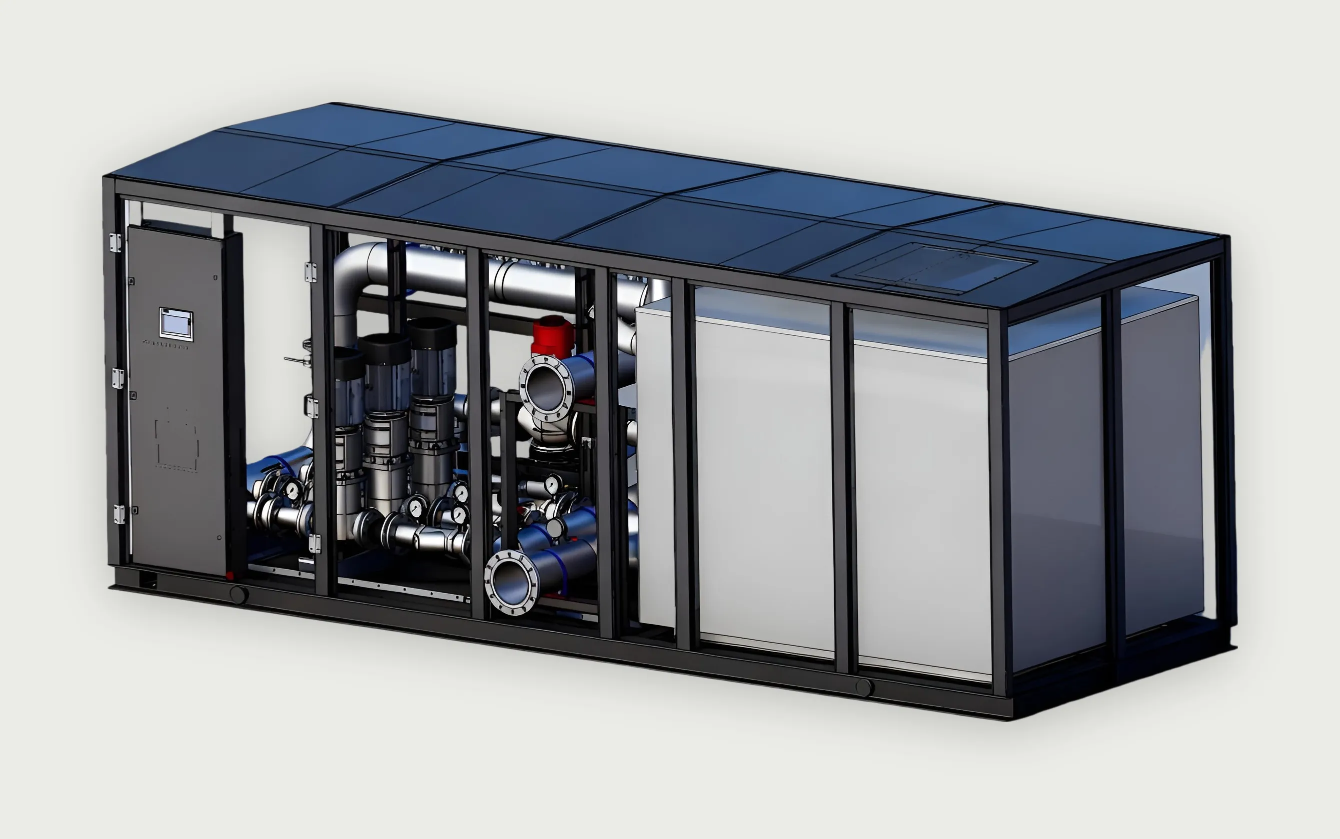
Cooling plant integrated and tested at the factory, then shipped as enclosures or base-frame assemblies.
Engineering challenge
Compute capacity is needed before a conventional mechanical plant can be built on site.
- Schedule set by compute
- Hardware delivery dates drive the programme. Site-built mechanical plant is frequently the longer path.
- Site integration risk
- Each pipe joint and cable termination made on site is work that cannot be tested until late in the project.
- Constrained or temporary sites
- Some deployments have no plant room, or need capacity that can be placed outdoors or relocated.
LINKWAVE response
How the system is built.
- 01Factory-integrated assemblies
- Pump stations are built as complete enclosures. Racks, CDU and switchgear can be assembled on a common base frame, as in the 2.5 MW United States reference.
- 02Tested before shipment
- Performance testing, functional testing and the factory acceptance test are completed on the assembled system.
- 03Defined site interfaces
- On site, the work is reduced to placing the assembly and making the hydraulic, power and communication connections.
System architecture
Where the work happens in the loop.
The same chain applies to every project. What changes is where capacity, redundancy and control are placed.
IT loop
01 / 09 · Heat source
GPU / CPU
By others
Processor heat flux sets every downstream requirement: coolant supply temperature, flow per server and allowable pressure drop.
02 / 09 · Chip-to-liquid heat transfer
Cold plate
Interface
Coolant passes through a plate mounted on the processor. Its flow and pressure-drop figures are the design inputs for the manifold and CDU.
03 / 09 · In-rack distribution
Rack manifold
LINKWAVE scope
A stainless manifold in each rack divides supply flow between servers and collects the return through 12 mm EPDM hoses.
View productSecondary loop
04 / 09 · Local coolant distribution
Rack / in-row CDU
LINKWAVE scope
Where load is distributed or facility water is unavailable, a CDU at the rack or row conditions and circulates coolant close to the IT equipment.
05 / 09 · Technology cooling system
Secondary cooling loop
LINKWAVE scope
Sanitary-grade stainless aisle piping carries treated water between the racks and the CDU. Typical supply and return: 40 / 55 °C.
View product06 / 09 · Loop isolation and control
Centralized CDU
LINKWAVE scope
A plate heat exchanger separates the IT loop from facility water. Dual variable-speed pumps hold flow and pressure. Reference units: 500 kW and 2.5 MW.
View productPrimary loop
07 / 09 · Facility water system
Primary cooling loop
LINKWAVE scope
Facility water carries heat from the CDUs to the heat-rejection plant. Water quality is managed by make-up, dosing and filtration on this side.
08 / 09 · Primary circulation
Primary-side pump station
LINKWAVE scope
Skid-built pumps with variable-frequency drives, storage, make-up and dosing. 125 kW to 2.5 MW, 10–250 m³/h.
View product09 / 09 · Heat rejection
Dry cooler / cooling tower / chilled water
Interface
Three reference arrangements: isolated CDU with chilled water; isolated CDU with cooling tower and pump station; direct-connected CDU with dry cooler and online purification.
Heat travels from chip to heat rejection. Select a stage for detail.
Heat-rejection arrangements
- Isolated CDU + chilled water
- The CDU exchanges heat with an existing chilled-water system. Suited to facilities that already run a chiller plant.
- Isolated CDU + cooling tower + pump station
- A primary-side pump station, including a dosing unit, circulates facility water between the CDU and a cooling tower.
- Direct-connected CDU + dry cooler
- The CDU connects directly to a dry cooler, with online purification maintaining water quality in the single loop.
Planning a liquid-cooled facility?
Send the load, rack density and facility constraints. An engineer will respond with an architecture and the open questions.